
One of my side projects is water drop photography. The kind where you capture two or more droplets crashing into each other at the right moment.
You can get some good results by hand, but things get really exciting when you automate everything then make minor adjustments to the timing and light.
So, how do you trigger the camera at the right time? I used an Arduino, but you can use anything that you can program to turn on an LED such as a Raspberry Pi.
I'll explain how you can make a simple circuit to trigger your camera that becomes as simple as turning on an LED.
What you need
- Camera
- Shutter remote
- Microcontroller, wires and a resistor
- An optocoupler
I use an Arduino and a Nikon D7000 so I will talk about those. This applies to other cameras or microcontrollers too.
What is an optocoupler?
This is the key part we will be using to connect the camera to the Arduino.
An optocoupler is a chip that connects circuits together in an isolated way. On the inside is an LED and a photo transistor.
When you light up the LED, the resistance changes on the other side allowing current through, just like a switch.
There are other parts you could use but an optocoupler is ideal because of this isolation.
Remotes
There are two options for the Nikon D7000. A cable remote, or an infrared remote. I use both. The the cabled version is the simplest so that's what I will talk about here.
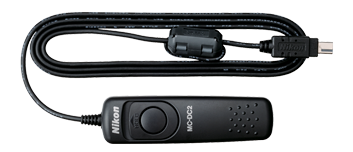 Nikon MC-DC2
At its core the cable release remote is just a plug, wires and a switch. It's a wonder why they are so expensive. Since we want to pull it apart, I recommend buying a knock off from eBay.
Yank it apart to expose the wires.
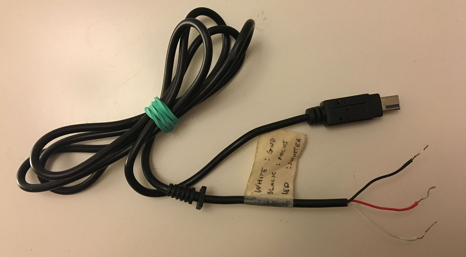
For my remote, there are three wires. A ground wire (white), focus wire (black) and shutter release wire (red). When the focus wire is connected to the ground wire, the camera will try to autofocus. Then when the shutter wire is connected to the other two wires, the shutter will go off.
A quick Google search and you can find out what the pins do for your remote. Your wires may be different colours.
The microcontroller
The first thing typically tried with a microcontroller is to make an LED blink. If you can make this work you can trigger your camera.
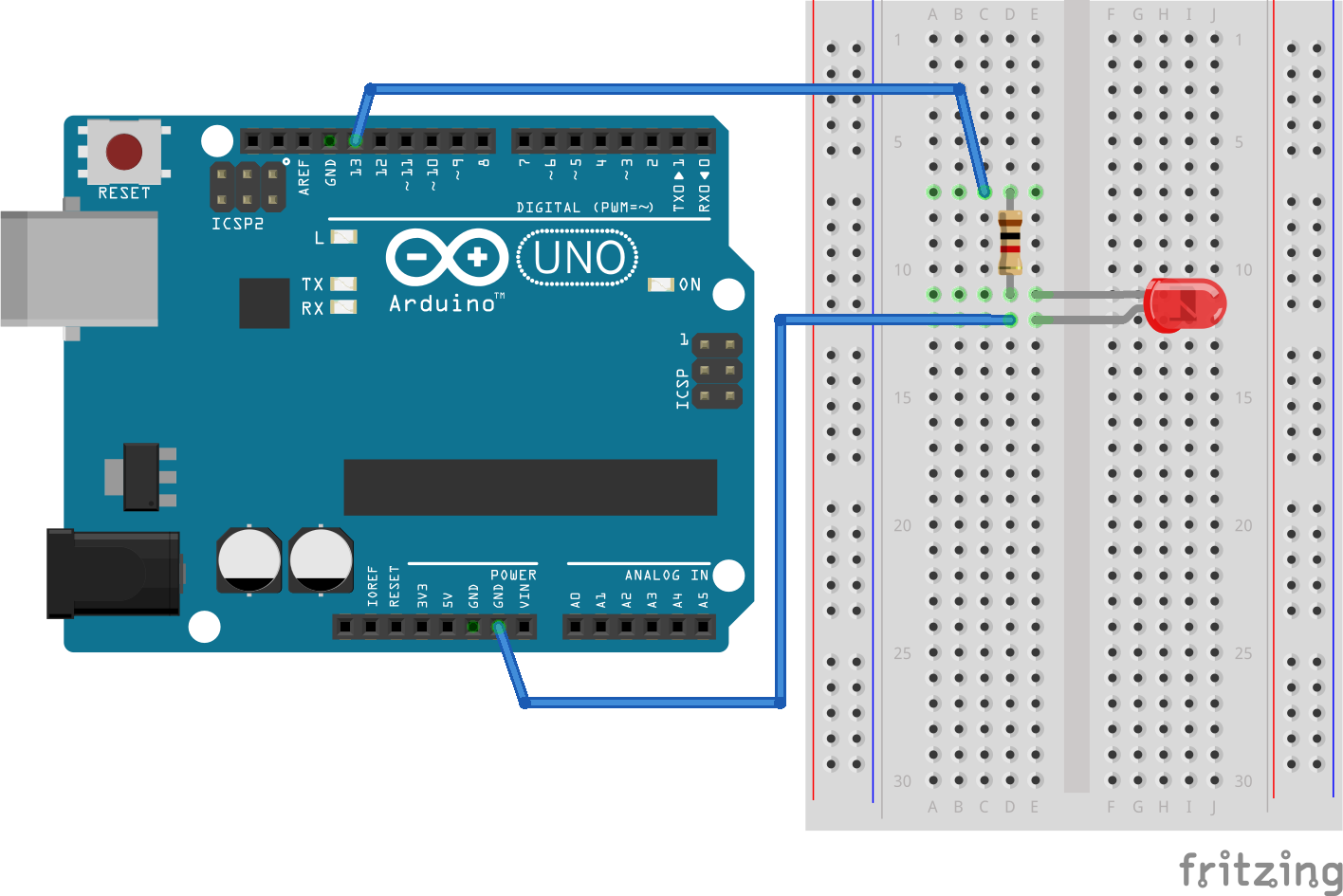
It doesn't matter what board you use, so long as it has output pins and you can make them drive an LED.
Putting it all together
The optocoupler is used to create a bridge between Arduino and the camera remote.
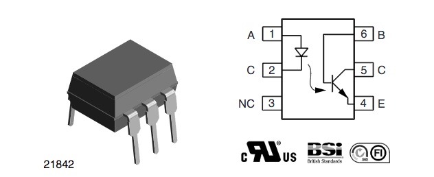
Refer to the datasheet to see what the pins mean.
On the left of the circuit digram is the LED with an anode (+) and cathode (-). On the right is the photo transistor with a base, collector, and emitter.
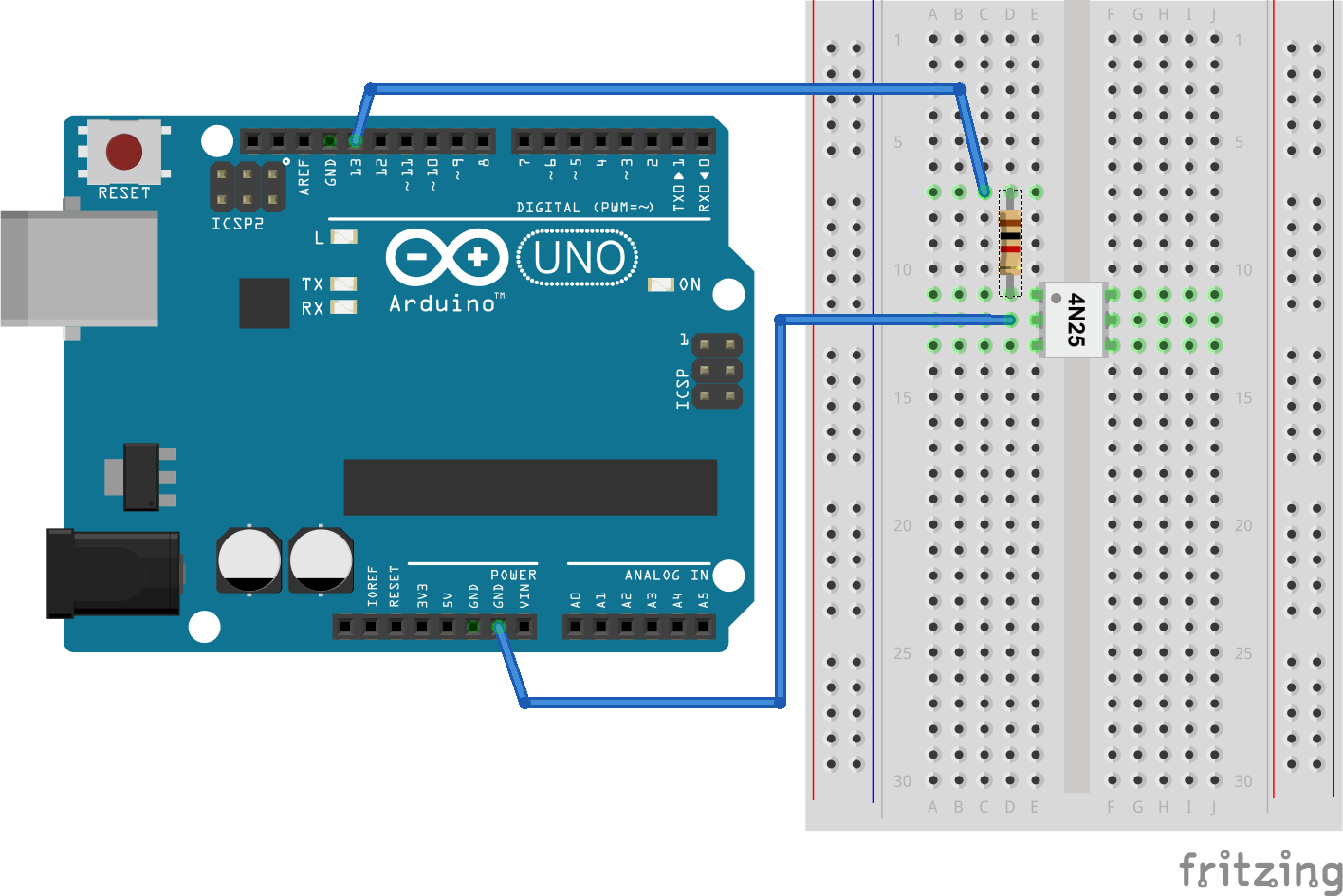
We wire up the LED in the optocoupler to the microcontroller the same way we wire up an LED. It needs a resistor in series so it doesn't burn out.
The same resistor you use to drive an LED will also work with this optocoupler. In my case a 1k resistor let through enough current to trigger the camera.
Plug the remote into the transistor side. The ground is connected to the emitter. The focus, and shutter wires are connected to the collector. We can ignore the base pin, it can be used to adjust the sensitivity of the photo transistor.
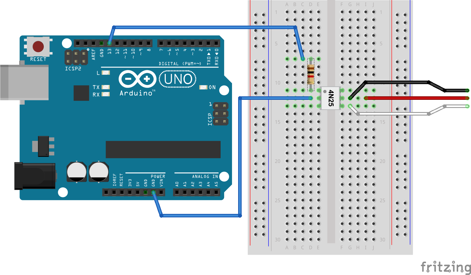
Since I was using manual focus, I left shutter and focus wires connected together. You could use another optocoupler and data pin to control the focus separately.
What's next?
Run your program and you can fire your camera by turning data pins on and off, the same way you control an LED.
You could write a program to trigger it with a timer, or sound, or light, or even when someone sends you a tweet.

Apply the same concept to an electric valve and you can take some interesting drip photos.
Tweet at me if you want to know more.
Update: I wrote a follow up post on how to hack an infrared remote.